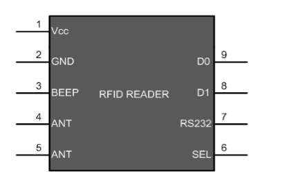
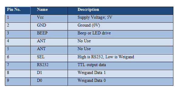
RFID INTERFACING WITH PIC
Radio-frequency identification (RFID) technology enables remote and automated gathering and sending of information between RFID tags or transponders and readers using a wireless link. Using RFID the exchange of data between tags and readers is rapid, automatic and does not require direct contact or line of sight.
Synopsis

Radio-frequency identification (RFID) technology enables remote and automated gathering and sending of information between RFID tags or transponders and readers using a wireless link. Using RFID the exchange of data between tags and readers is rapid, automatic and does not require direct contact or line of sight.

The RFID module can be interfaced with the board using the same serial reception program used for testing the UART. When a Card (tag) is brought near the RFID reader, it tries to communicate with the tag, receives the data and decodes it. Finally it send the data over the TX line. The UART module in MCU receives the data and thus used for further applications. By employing RFID, much secured entry systems can be developed without incurring huge costs. These are the reasons of excessive use of RFID technology.

Description

The EM-18 RFID Reader module generates and radiates RF Carrier Signals of frequency 125KHZ through its coils. When a 125KHz Passive RFID Tag (have no battery) is brought in to this field, will get energized from it. These RFID Tags are usually made using a CMOS IC EM4102. It gets enough power and master clock for its operations from the electromagnetic fields produced by RFID Reader.

RFID module consists of an RFID Reader, a line converter (usually MAX232) and a COM port. The line converter of this module converts the TTL logic voltage of RFID Reader to RS232 logic. Therefore, to convert the voltage level from such an RFID module, another MAX232 is used to interface it with a microcontroller.

One can also use an RFID Reader directly to interface with the controller, thus avoiding the need of voltage level converters. Here both the MAX232s have been eliminated from the circuit and RFID reader is directly connected with the PIC microcontroller.

RFID READER MODULE


Pin Description


With the RFID interfacing, this article also explains the USART interrupt which is an internal interrupt. (For external interrupts, refer PIC Hardware interrupts) The internal interrupts, unlike hardware interrupts, are associated with internal peripherals of the controller. To use the USART interrupt, following registers have to be configured accordingly.

INTCON (Interrupt Control Register)


PEIE/GIEL: This bit is used to enable/disable all the peripheral interrupts (Internal interrupts) of the controller. But GIE/GIEH bit must be set to high first.

1 = Enables all Peripheral Interrupts

0 = Disables all Peripheral Interrupts

GIE/GIEH: This is Global Interrupt Enable bit. This bit is set to high to enable all interrupts of the PIC18F4550.

1 = Enables interrupts

0 = Disables all interrupts

PIR1 (Peripheral Interrupt Request 1)
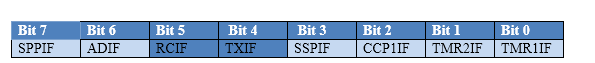

TXIF

This is Transmission interrupt flag which is set to high when TXREG* is empty.

RCIF

This is Reception interrupt flag which is set to low when reception is complete.

TXREG

EUSART Transmit Register (The data to be transmitted is stored in this register)

PIE1 (Peripheral Interrupt Enable 1)
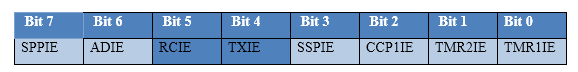

TXIE

This bit is used to enable/disable the Transmission (Tx) interrupt.

RCIE

This bit is used to enable/disable the Reception (Rx) interrupt.

Applications

• Product tracking

• Access control

• Logistics

• Asset management

• Identification

Proteus design for RFID interfacing with PIC


Orcad design for LDR interfacing with PIC


RFID interfacing with PIC

/*  Name     : main.c
 *  Purpose  : Source code for LDR Interfacing with PIC18F4550.
 *  Author   : Gemicates
 *  Date     : 2017-07-03
 *  Website  : www.gemicates.org
 *  Revision : None
 */

#include<htc.h>
#define _XTAL_FREQ 12000000                //12MHZ

#define LDR PORTA

void LDR_Init()
{
  ADCON0 = 0x41;                           //ADC Module Turned ON and Clock is selected
  ADCON1 = 0xC0;                           //All pins as Analog Input
                                           //With reference voltages VDD and VSS
}

unsigned int LDR_Read(unsigned char channel)
{
  if(channel > 7)                          //If Invalid channel selected 
    return 0;                              //Return 0

  ADCON0 &= 0xC5;                          //Clearing the Channel Selection Bits
  ADCON0 |= channel<<3;                    //Setting the required Bits
  __delay_ms(2);                           //Acquisition time to charge hold capacitor
  GO_nDONE = 1;                            //Initializes A/D Conversion
  while(GO_nDONE);                         //Wait for A/D Conversion to complete
  return ((ADRESH<<8)+ADRESL);             //Returns Result
}

void main()
{
  unsigned int a;
  
  TRISC= 0xC0;                             //PORTC as output
  LDR = 0xFF;                              //PORTA as input
  LDR_Init();                              //Initializes LDR Module

  do
  {
    a = LDR_Read(0);                       //Reading Analog Channel 0
    PORTC = a>>8;                          //Higher 2 bits to PORTC
    __delay_ms(60);                        //Delay
  }while(1);                               //Infinite Loop
}

Error message here!

Show Error message here!


Forgot your password?

Error message here!

Send OTP

Error message here!

Show Error message here!


Lost your password? Please enter your email address. You will receive a password you Need.

Send Error message here!


Back to log-in

Close